ANSI Pipe Marking Standards
ANSI Pipe Labeling and Marking Standards: What are OSHA's requirements?
Pipe marking standards are not specifically outlined or defined by OSHA, but standard number 1910.261(a)(3)(ii) notes the ASME's (ANSI) standard A13.1 as the recommended scheme for identification of pipe systems.
The ASME Standard for Pipe Identification is a widely used guideline in determining pipe identification requirements. The ASME A13.1-2020 notes indicate that, "A13.1 is intended to establish a common system to assist in identification of hazardous materials conveyed in piping systems and the materials’ hazards when released in the environment." It goes on to identify that this scheme provides pipe system identification recommendations for industrial workplaces, power plants, commercial and institutional installations and buildings used for public assembly.
Pipe Color Code Chart - ANSI/ASME A13.1
Why Pipe Markers Matter
Industrial environments carry with them complex networks of pipes carrying various substances – everything from steam to water to hazardous chemicals. If a leak occurs, pipes can release dangerous energy or substances into areas containing people, equipment and other potentially dangerous substances. Without clear pipe markers, time is lost identifying pipe contents and the appropriate emergency response, putting workers and the facility at risk. In addition to safety concerns, clear pipe markers facilitate more efficient maintenance and routine operations. Effective pipe marking isn’t just about compliance or organization. It's about safeguarding lives, protecting assets and ensuring operational efficiency.
| Label Color | Text Color | Example | Pipe Contents |
|---|---|---|---|
| Red | White | Red | Firefighting |
| Orange | Black | Orange | Toxic or corrosive |
| Yellow | Black | Yellow | Flammable, combustible or oxidizing |
| Gray | Black | Gray | Steam; or steam condensate, boiler feedwater, or other hot water |
| Green | White | Green | Potable, cooling, or other cold or tepid water |
| Blue | White | Blue | Compressed air |
| Purple | White | Purple | To be defined by the user |
| White | Black | White | To be defined by the user |
| Brown | White | Brown | To be defined by the user |
| Black | White | Black | To be defined by the user |
GHS Pictograms
The inclusion of GHS pictograms were added to the 2015 revision of ASME A13.1 - “Applicable GHS pictograms may be included as part of the legend. Where piping is connected to containers that are labeled in accordance with GHS requirements, a corresponding label on the piping may be provided. The corresponding label should contain at least the product name or identifier, the pictogram, the signal word, and the physical, health, and environmental hazard statement(s).

- Oxidizers

- Flammable
- Self-reactives
- Pyrophorics
- Self-heating
- Emits flammable gas
- Organic peroxides

- Explosives
- Self-reactives
- Organic peroxides

- Acute toxicity (severe)

- Corrosives

- Gasses under pressure

- Carcinogen
- Respiratory sensitizer
- Reproductive toxicity
- Target organ toxicity
- Mutagenicity
- Aspiration toxicity

- Environmental toxicity

- Irritant
- Dermal sensitizer
- Acute toxicity (harmful)
- Narcotic effects
- Respiratory tract irritaion
Pipe Marker Visibility and Size Requirements
The ANSI standard A13.1 on pipe marker visibility and size requirements was updated in 2020, resulting in slight changes from the previous (2015) requirements. When considering the size and placement of lettering on your pipe marker, consider that, “Attention should be given to the visibility of the pipe markings. Where pipelines are located above or below normal line of vision, the lettering should be placed below or above the horizontal centerline of the pipe.”
| Outside Diameter of Pipe or Covering | Length of Color Field | Letter Height |
|---|---|---|
| 0.7 in-1.3 in (18-33 mm) | 8 in (203 mm) | 0.5 in (13 mm) |
| 1.4 in-2.4 in (34-61 mm) | 8 in (203 mm) | 0.7 in (19 mm) |
| 2.5 in-6.7 in (62-170 mm) | 12 in (305 mm) | 1.3 in (32 mm) |
| 6.8 in-10 in (171-254 mm) | 24 in (610 mm) | 2.5 in (64 mm) |
| Over 10 in (Over 254 mm) | 32 in (813 mm) | 3.5 in (89 mm) |
What if your pipe or covering outside diameter is less than 0.7 inch or 18 mm?
In cases where it is difficult to label a pipe or covering due to size, we advise using durable and long-lasting energy source or valve tags in place of pipe labels or markers. Now that we know what our pipe labels need to look like and how big they need to be, we need to understand where they go.
Pipe Marker Content
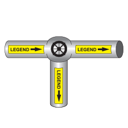
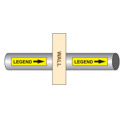
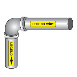
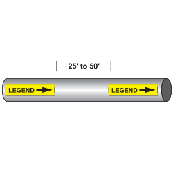
Effective pipe markers provide critical content at a glance. This includes the name or abbreviation of the contents of the pipe for quick identification, directional arrows indicating flow direction to understand the system's layout, and any additional safety symbols or warnings to alert workers of potential hazards. Maintaining clarity and conciseness is key, ensuring information can be understood quickly and from an appropriate distance. Additionally, a comprehensive pipe marking system includes the use of valve tags to tie back to and reinforce pipe marker content. For more information on how pipe marking and valve tagging work together, check out our guide on valve tagging standards.
Pipe Marker Placement